
Ackerman Steering
How do cars turn corners? Whether driven by the front wheels or the back, cars are steered by turning the front wheels.*
|
*Why? It’s a stability issue. If they were steered from the rear, minor deviations in angle would be amplified with positive feedback, increasing further the angle. It’s like the difference between dragging a pencil across a table by the tip of your finger, or attempting to push it across with your finger from behind. |
Before cars, we had carriages, typically pulled by horses. These had large open wheels.
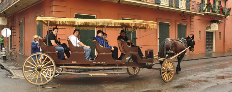 Image: Venson Kuchipudi
|
Short wheelbase carriages had fixed wheels, relying on slippage of the skinny wheels to compensate by skidding when pulled by the horses, but maneuverability at slow speeds, and tighter corners, or longer wheelbases, was enabled by steering the front axle. This first kind of simple steering is often called “Turntable Steering”. There’s a single pivot in the center of the front axle. Both the front and rear axles are solid. |
 |
 |
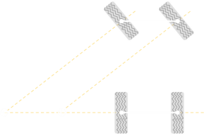
By rotating the front axle, the geometry is adjusted so that both axles are pointing towards a common point. Each wheel travels around in a circle with a common center (albeit it with different radii), removing the need for side-slip or skidding. In a simple carriage, each wheel is independently free-wheeling, and the traction force is not provided by the wheels, so the differences in the circumferences is compensated by each wheel having a slightly different rotation rate. If the vehicle were travelling over a muddy field, you might see four circular arcs as it turned. |
This is an elegant solution for maneuverability, but it has quite a few problems: The axle has to swing through large arcs to make turns, and this reduces the usable space inside the wheelbase (or requires the occupied space to be high above both axles). It’s a single stress point, making the addition of suspension challenging, and the long axle acts like a lever amplifying small variations in road surface.
|
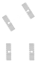
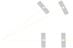
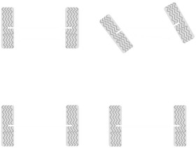
The next solution is simple steering. Here, each wheel is given its own pivot. This solves some of the problems above, but we get the return of the side-slip issue. It’s certainly better than a totally fixed front axle, which requires a lot of sideslip but, by turning both wheels the same angle, we can see that each of the front wheels has a different center of rotation. With simple steering, at least one of the front wheels will be experience side-slip. This is a problem. If we imagine a vehicle with simple steering maneuvering over a gravel driveway, on every turn, irrespective of speed, the front wheels would plough through the gravel leaving unsightly ruts, and require excess traction power to overcome this additional friction compared to simply rolling along. |
 |
Ideal Solution
 |
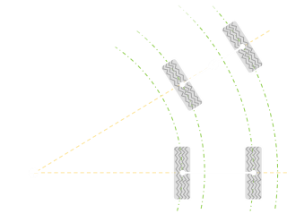
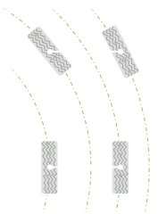
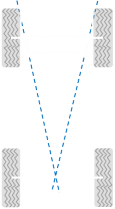
The ideal solution would be for each of the front wheels to be independently steerable. In this way, each could be set to the perfect angle to make a tangent to the circular arc with a common center. |
|
With each wheel running on a circular arc of the correct radius there should be no side-slip. To deal with the issue that the different, powered, wheels runnig at different rotational speeds the drive train typically has a differential placed in the axle (probably a topic for a future blog posting …) |
 |
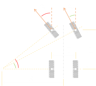 |
Here's the ideal setup. We can see that, when turning, the inside wheel turns with a larger angle than the outside.
|
If we assume constant speed (no weight transfer or external forces), no body roll or suspension effects, and only the front wheels steering then we can use simple trigonometery to find the ideal angles for the wheels:

Here are these angles plotted, parametrically, on a graph. Using some example constants for L and T, on the x-axis, is the plotted the internal wheel angle, and on the y-axis is plotted the external wheel angle (both angles plotted in degrees) that corresponds to a range of possible curve radii.
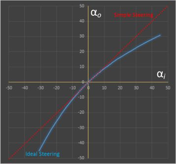 |
The red line shows the relationship between the two wheel angles for simple steering; here both wheels turn in parallel so the result is a straight line with unity gradient. The blue line shows the relationship between the two wheel angles for ideal steering. For all radii of turns, the absolute value of the internal angle is always higher than than that of the outside angle. The tighter the turn, the higher the ratio of the internal to outside angle. |
This blue lines shows the ideal relationship between the two angles, but it's not a simple relationship. The challenge for how to create a mechanism to turn the wheels in this way is the problem solved by the Ackerman solution.
Ackerman Steering
An elegant and simple mechanism to approximate ideal steering was patented in England in 1818 by Rudolph Ackerman, and though it is named after him, the actual inventor was a German carriage builder called Georg Lankensperger who designed it two years earlier.
 |
In Ackerman steering, each wheel is given its own pivot (which is typically close to the hub of the wheel). Tie rods create a trapezium shape with two additional pivots. As the shape is a trapezium, as the inside wheel turns, the outside wheel turns at a different rate. By adjusting the geometry (length of the tie rods and angle they form with the straight ahead), the relative rotations of the wheels can be configured. If the track rod joining the two wheels is the same length as this distance between the two pivots, then the rectangle they make deforms to a parallelogram as the wheels turn, and the configuration is the same as simple steering, and the both wheels turn at the same rate. |
As the track rod is made shorter ("toe-out") than the axle, then the inside wheel turns at a higher rate as the trapezium deforms.
The equations for the value of the wheel angles based on the rod lengths and initial angles are more complex calculations than first might appear. If you want to read more, look into Freudenstein four bar linkage configurations. The Ackerman steering system only provides an approximate solution to the ideal steering condition.
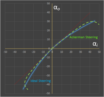 |
To the left you can see an example of how close the Ackerman steering geometry conforms to ideal steering. In 1878, a Frenchman, Charles Jentaud, applied the Ackerman principle to his mechanical propelled vehicle, and found that best results are obtained when a projection of the edges of the trapezium intersect over the rear axel.
|
Ackerman steering solves most of the problems of turntable steering: The space required (fore-and-aft travel) by each wheel is significantly reduced, and the moment arm transmiting back imperfections in the road is reduced.
For small steering wheel inputs, the difference between the wheel angles is small. As the radius of the required turn decreases, the difference in angles increases (you may have noticed that, when you turn the wheel of the car at to full-lock, such as when parking, the difference is very noticable).
 Image: Pasimi
Slip Angle
All of the above calculations are applicable to slow speed. However, when we need to consider vehicle dynamics, things get more complex. When a vehicle is in motion, in a turn, the tyre deforms, and there a difference between the direction of travel, and the direction the tyre is pointing. This is called the slip angle.
Professional racers adjust the Ackerman configuration of their vehicles to balance needs. There is a limit to the grip that any tyre can provide, and depending on the difference between the slip at the front or rear of the vehicle understeer or oversteer can be created. Some drivers even configure their vehicles with neutral-Ackerman (simple steering), or even anti-Ackerman geometry, to reduce heating in the their tyres, and tyre load.
You can find a complete list of all the articles here. Click here to receive email alerts on new articles.
© 2009-2016 DataGenetics Privacy Policy