

Newsletter: Click here to join an email list and be contacted when a new article is published.
Advertisement |
|
Linear Feedback Shift Registers
This article is about Linear Feedback Shift Registers, commonly referred to as LFSRs.
An LFSR is like a black box into which you feed a number, and the generated output is some linear function of the input (typically created by some combination of shifting, and Exclusive-OR, of the bits).
They are deterministic; the same input will always give the same output. They have lots of cool uses, but first let’s take a look at how they work. The particular kind of LFSR I’m going to model today is called a Galois LFSR, named after the French mathematician Évariste Galois (who tragically perished after being shot in a duel at the young age of just 20).
Galois LFSR
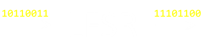
The diagram below shows a binary representation of a 16-bit Galois LFSR. The basic premise of the LFSR is that all the bits of the input are shifted right one position. Some bits are shifted, unchanged; however, some bits potentially change by the application of XOR operations. The bits that could change are called taps, and these taps provide one input into a two-input XOR gate. The other input to the gate is provided by the LSB of the input stream that will get shifted off the end with the operation.
 Image: Wikipedia. In this LFSR there are four taps: 16,14,13,11 (The tap at 16 does not need a gate as the other input is always zero as as result of the shift).
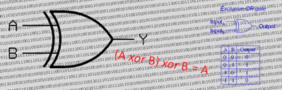
An exclusive-OR gate (XOR), is a very common component in electronics. The easiest way to think about it is with the phrase ”One or the other, but not both”. It has many interesting uses in electronics and computer science (particularly as applying the XOR function twice in a row with the same value returns a number to its original state). A truth-table, and symbol, for a two-input gate is show here.
 |
|
Because of the way these gates are applied, if there is no tap, each bit is shifted along unchanged. If there is a tap, and the LSB of the number is set, these tapped bits are inverted before being shifted over. If the LSB is not set, the tapped bits are shifted unchanged.
Here is a fragment of pseudo code showing an LFSR function:
if (n & 1) { n = (n >> 1) XOR t; } else { n = (n >> 1); }
It really is pretty simple. If the LSB is set (n & 1) then shift over one position >> and XOR with the tap mask. Otherwise just shift it over.
The result of these shifts is that, for a given input, a new output is generated (providing the input is not zero; if all the bits on the input are zero, the output will also be zero).
Cycles
The new output can be fed back in to generate a new output, and so on.
For a given input, eventually the number returns back to the starting number in a loop (each output is determinsitic from the input). Below is an example of a four bit LFSR, seeded with the number 1 (the left most box in the animation below).
In this example, the tap mask is set to 1010, and applying the LFSR transitions it to 10, then 5, 8, 4, 2, and back to 1

After a cycle of six, the input returns to 1 and some combinations are unvisited.
There are certain “magic” tap masks that create an optimal cycle in which every bit combination is visited in the cycle. For a 4-bit register, one of these masks is 1001. No matter what the input (providing it is not zero), the LFSR will cycle around through all 15 numbers 1-15 and return to the starting point. Below is an animation of this happening.

This cycle is: 1, 9, 13, 15, 14, 7, 10, 5, 11, 12, 6, 3, 8, 4, 2
(There are only two bit patterns that generate perfect 4-bit LFSRs, the other is 1100).
Perfect LFSRs are incredibly useful, as they provide a pseudo-random shuffling of all the numbers. Every combination of bits will have been passed through, and all that is needed is just a couple of low-level instructions (and better still if you are implementing in hardware; all you need is a couple of logic gates, and the next number can be generated on the next clock tick).
You can be sure that every number will be seen without having to keep a track of what has been seen already, and you don’t need to keep an array in memory for the order to visit things.
The bits come out in pseudo-random order; they are not totally random (after all they are mathematically determined based on the input), but they are sufficiently mixed up so that, to the casual eye, they are random. As they are in a cycle, each number appears once so they are perfect for generating white noise.
If you were writing test cases and wanted to expose your code to all possible inputs, but not in sequential order, you could use a perfect cycle LFSR. If you wanted to ensure you’d cycled through them all (a perfect Hamilton cycle), even if you used a clever trick like a De Bruijn Sequence, you’d still need extra memory, but not with an LFSR approach.
Probably one of the most contemporary uses of LFSR is in the Fizzle Fade, famously popular in the Castle Wolfenstein game. Here the idea was to gradually fill the screen with blood as the player died, in some random order. Each pixel only wanted to be visited once, but the expense of shuffling would have been a waste of memory and processing time (Even if done correctly, the Fisher-Yates way).
If you attempted to do it using a purely random approach, there's no easy way to remove already visited pixels from the next selection.
An LFSR solution is perfect for this. Early game consoles were short on memory and these pseudo-random techniques were also used to generate 'random' configurations for rooms/dungeons and maps.
LFSR have use in cryptography, as an obfuscation technique. I'm hesitant to say securely, because, being mathematically determinstic, they are easy to crack, but they are useful for adding "entropy" to otherwise obvious blocks of contiguous data to obfuscate them, or to garble or obscure transmissions that, otherwise, in the clear would be obvious to the human eye/ear. XORing a stream of data with an LFSR, before transmission, would really mess it up to the casual observer, and it's trivial to remove it again by repeating the XOR operation (providing you know the tap mask and starting value), and the logic (or electronics) to perform this operation is very, very simple.
Finally, again at a hardware level, it is possible to use an LFSR as a simple "clock signal" generator. In certain appplications it might not be important that the clock is incremented in binary. The electronic logic to produce an increasing binary clock signal is complex, involving many gates. As we've seen the logic to produce the next LFSR value, in contrast, is really simple. If the application simply requires a deterministic, distinct, clock signal generator, then an LFSR might fit the bill nicely.
Try it out
Below is an interaction that will allow you to experiment with 8-bit LFSR.
Instructions:
Click on the next button to advance the LFSR to the next value.
The top boxes show the input (click on any box to manually change it).
The lower boxes show the configuration of the taps.An "X" indicates that XOR will be applied.These can also be manually toggled by clicking on them.
The connections button toggles the display of showing which values affect the next.
When in color mode, the colors represent will be passed to each cell on the 'next' cycle.
To the right is show the current value, the next, and the previous value.
The randomize button simply sets the inputs and tap positions to random values
The show bits adds an overlay to easy interpretation of the binary numbers.
If you want to try them out, here are the 16 perfect LFSR tap positions for 8-bit numbers.
| 10001110 | 10010101 | 10010110 | 10100110 |
| 10101111 | 10110001 | 10110010 | 10110100 |
| 10111000 | 11000011 | 11000110 | 11010100 |
| 11100001 | 11100111 | 11110011 | 11111010 |
Optimal Length LFSR
Maximum length LFSR (perfect LFSR taps) are known up to 32 bits. Here is an excellent source to find more details.
| Bits | # Perfect Solutions |
|---|---|
| 4 | 2 |
| 5 | 6 |
| 6 | 6 |
| 7 | 18 |
| 8 | 16 |
| 9 | 48 |
| 10 | 60 |
| 11 | 176 |
| 12 | 144 |
| 13 | 630 |
| 14 | 756 |
| 15 | 1,800 |
| 16 | 2,048 |
| 17 | 7,710 |
| 18 | 7,776 |
| 19 | 27,594 |
| 20 | 24,000 |
| 21 | 84,672 |
| 22 | 120,032 |
| 23 | 356,960 |
| 24 | 276,480 |
| 25 | 1,296,000 |
| 26 | 1,719,900 |
| 27 | 4,202,496 |
| 28 | 4,741,632 |
| 29 | 18,407,808 |
| 30 | 17,820,000 |
| 31 | 69,273,666 |
| 32 | 67,108,864 |
You can find a complete list of all the articles here. Click here to receive email alerts on new articles.
© 2009-2017 DataGenetics Privacy Policy