
Gray Code
|
Digital computers, at a fundamental level, work in binary. Voltages are present across wires, or they are not. We call this base-2, or binary, because there are just two states that any element can be in. Traditionally, when we count in binary, we mimic the way we count in other bases, such as decimal, with the least significant digits on the right, and the most significant on the left. |
 |
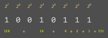 |
In traditional binary notation, each digit position we move over to the left is a new power of that base. This makes numbers easy to compare, add, and to perform other logical operations on because the columns have defined meaning and have similar properties related to the same digit being in the same position. This consistent place-value notation is given the name positional notation. A well known example of encoding numbers that does not use positional notation is Roman Numerals. The ancient Romans must have had the patience of saints to perform arithmetic using their notation! |
|
In any number base there are a plurality of ways that numbers can be encoded. We could even do it in an arbitrary way if we wanted! As long as each encoded number pattern is distinct and the encoding is repeatable it can be used to record a numeric value. (It’s also helpful if the encoding scheme is predictable and describable, so we don’t need a decoding/lookup table to interpret). One of the alternate systems for encoding binary* is called Gray Code (also known as reflected binary code) after the physicist Frank Gray. It has many interesting properties. But, we’re getting a little ahead of ourselves here, let’s get back to basics … |
 |
*It’s possible to create Gray Codes using other bases too, as we will see later.
Binary
|
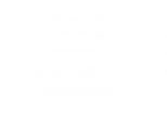
Systems based on binary are simple and easy to build. As mentioned above, computers use combinations of logic gates where the presence, or not, of a voltage indicates state of any bit. Binary signals are unambiguous; a value is either set, or it is not. There is no concept of 'half-set'. This immunity to noise is a great advantage. However, whilst there is no ambiguity with regards to what any individual bit can be set at (it has to be quantized to one of two values), there is the potential (when there is more than one bit in parallel) that not all bits change state at exactly the same time. As an example, look at the binary sequence to the left, which shows the binary representations of the decimal numbers 0-7. In red, we see the number 3 represented as 0112. As it changes to 4, every bit changes state, to 1002
(The subscript 2 being used to signify the number base to avoid confusion with decimal). Every value changes from either 1 to 0, or 0 to 1. If all of these bits changed instantaneously, and synchronously, from one state to the other, there would never be any problem, but outside of theory, that never happens! In the real world, some bits would flip before others. Since every bit is changing in this example, depending on the order they change, and depending on when you read their state, it might be possible to read any value from this collection of bits!! This kind of problem is called skew. Microprocessors solve this problem by have a clock. A clock is like a metronome and beats with regular cadence. Bits are allowed to change state, taking their own time as they do, but are only read when the clock next beats. The clock frequency is chosen so that each bit has had sufficient time to change state, settle, and then be read in a repeatable and consistent way. |
Gray Code
 |
This is the perfect segue to Gray Code. Gray Code is an alternative binary representation, cleverly devised so that, between any two adjacent numbers, only one bit changes at a time. If there is an error reading any bit that has changed then, at worse, the read value will never be out by more than one unit. |
This has tremendous value in the real world. Computers might be digital, but we live in an analog world. Interfaces between these need to be carefully considered.
Look at this fictitious example below. Here is a depiction of a moving belt that we want the computer to know the position of to a defined granularity. If we painted symbols on the belt using binary (carefully selecting the width of the painted symbols and the number of bits for the resolution and accuracy we wish to measure), in a perfect world, there would be no problem.

However, if you look at the diagram, you'll see that the sensor bar is not perfectly aligned, and some bits will probably flip before others (and even with the bar were perfectly aligned, in reality, each sensor is not going to flip at exactly the same time, so there would be doubt over the value read).
This could result in 'garbage' readings, and these bogus readings could be equated as positions far away from the true position. If some bits change state before the others, and you read at this mixed state, you'll get an answer that is neither the first, nor the second expected result.
|
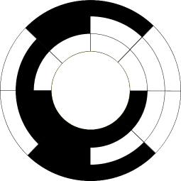
To the left we see three columns of data. These are representations of the same numbers 0-31 in different ways. In the middle is the decimal value. On the left is positional notation binary (the vanilla binary we know and love), and on the right is Gray code (reflected binary notation). You will notice that, on the right, each adjacent row is different from it's neighbours by no more than one bit. If these codes were passed through some kind of analog to digital conversion process (like the belt above), either the correct answer, or an answer just one unit away from the the correct answer would be obtained on any read. It's not just linear conversions of course, here is a example application of a three-bit rotational shaft encoder.
This sensing arrangement could be used to determine the orientation of a shaft in 45° increments using just three sensors. |
Pretty pictures
Here is a diagram showing 128 binary values (7-bits) ranging from 00000002 on the left to 11111112 on the right. It's a pretty picture, and as you can imagine it is recursively self-similar. The red pixels depict a set bit.

Below is a similar plot, but this time depicting Gray code. It's an interesting pattern:

A subtle, but kinda obvious when you think about it, observation is that there is no bit that directly toggles on/off in two adjacent steps in Gray code. The bottom row has bits that are on/off for two time segments, not one cf. the binary version which alternates. If this were not the case, then there is no way the we could get through the numbers only changing one bit at a time. The bit on the bottom row changes, it's held there whilst another bit is changed on the next step, then it can be toggled back …
In the next row up, the bit is set on/off for four time slices at a time, then next row up eight …
It's all about the base
|
It's possible to create Gray codes for higher number bases (no trouble). To the right is an example of a Gray code based on ternary (base-3). As with binary Gray code, each row differs from those either side with the change of just one digit. Also, the digit that changes, only changes by one unit. There are multiple ways to generate Gray codes to produce solutions that don't need to be reflectively balanced. Some of these have interesting characteristics. Up until now, all the codes we've described have been cyclic in nature; wrapping around consistently from the end back to the beginning. It's possible to generate Gray codes without this restriction (though to be honest, I can't understand the value of this, as the step-change on the warp around would experience the exact problem we are trying to solve!)
|
000 → 000 001 → 001 002 → 002 010 → 012 011 → 010 012 → 011 020 → 021 021 → 022 022 → 020 100 → 120 101 → 121 102 → 122 110 → 102 111 → 100 112 → 101 120 → 111 121 → 112 122 → 110 200 → 210 201 → 211 202 → 212 210 → 222 211 → 220 212 → 221 220 → 201 221 → 202 222 → 200 |

Balance Gray Code
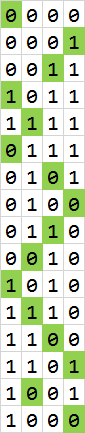 |
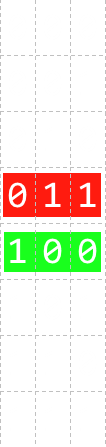
A different sub-class of Gray codes are described as Balanced Gray codes. These have the intresting property that there are the same number of state transitions per bit. Take this example on the left for a 4-bit code. As with all Gray codes, each row differs from the row above and below by just one digit change. However, this code has the interesting property that each bit changes state exactly four times. It is uniformly balanced. The green squares show the location where each bit toggles state. This property has advantages in the physical world. Imagine, for instance that, instead of light sensors in our belt example above, a machine was using physical switches for each of the bits to convey state. If the vanilla reflective binary Gray code were used, some switches would get considerably more use and wear than others. As physical switches have a finite life, it is more likely that the heavily used switches would fail first. By using a balance Gray code, each switch can be utilized to the same number of on/off operations in a complete cycle. Each switch will, therefore, experience approximately the same wear. It's not always possible to make a perfectly balanced cycle. With four bits, there are 16 signals to make, so each switch can experience four transitions. With five bits, there are 32 combinations to encode, but 32 does not divide equally by 5, so there will need to be asymmetric uses of the switches. (Outside the scope of this posting, but it is possible to generate balanced Gray code systems if there are an even number of bits). |
You can find a complete list of all the articles here. Click here to receive email alerts on new articles.
© 2009-2014 DataGenetics Privacy Policy