
String Selfie
A little while ago I saw a piece of artwork that was generated using a single thread wound around a collection of pins in a, seemingly, ‘random’ arrangement. Where this thread passed over the same location multiple times it created contrast, and these patches of contrast blurred together to make an image. It was very cool.
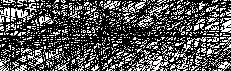
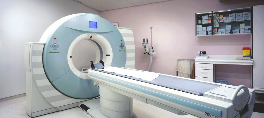
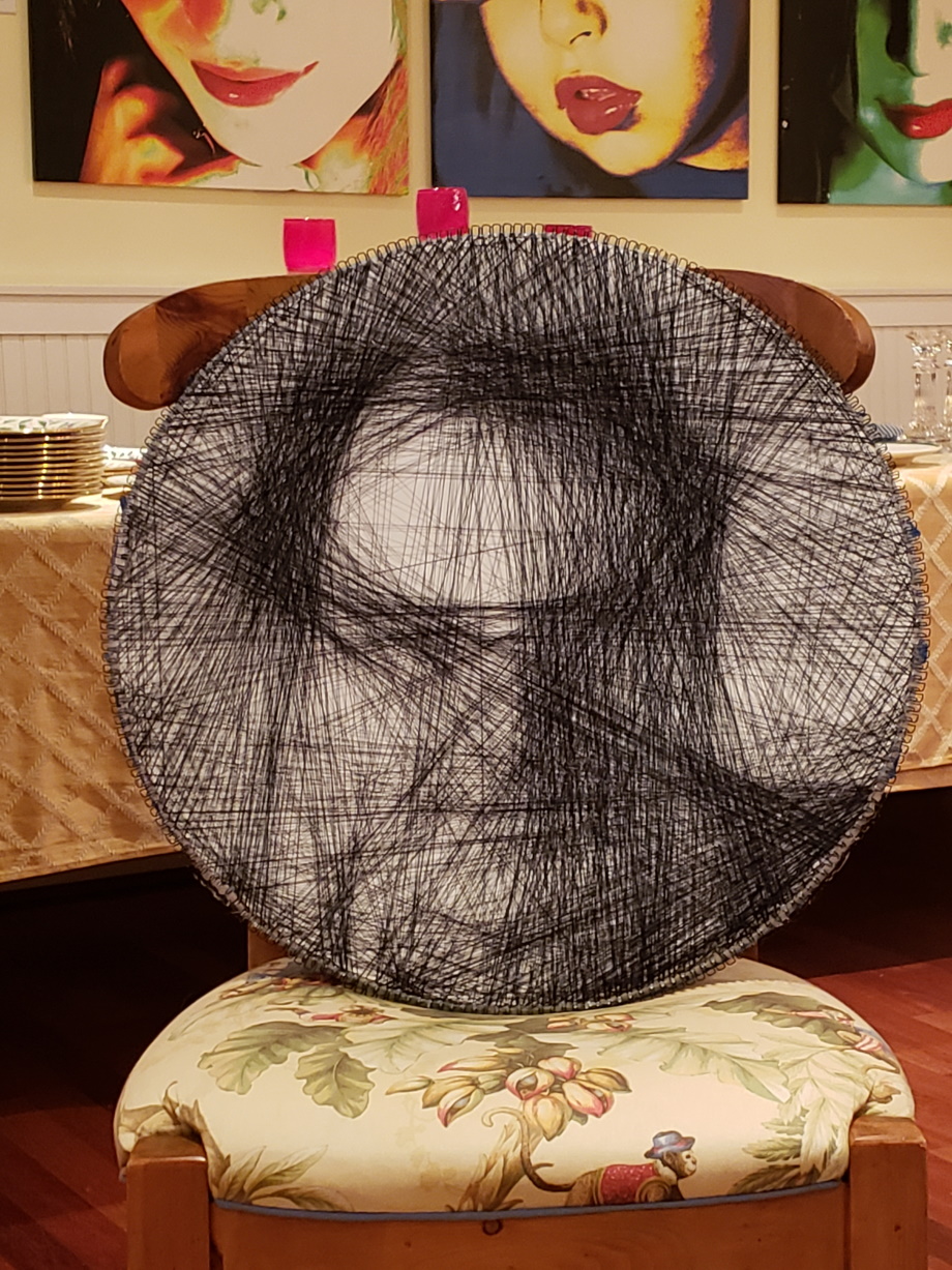
I thought it was very nifty and promised myself that I would have a go at making one myself sometime in the future. Then I forgot about it. I was reminded about the project, of all times, as I was getting a CT scan to check on the progress of my medical condition. (Below is a close-up of the threads of a string art image).
CT (or Computer Assisted Tomography), was invented as a mechanism for, non-invasively, viewing the internal structure of the human body (or other object). The inventors, Allan M. Cormack and Godfrey N. Hounsfield, received the Nobel prize for their work in 1979.
CT works by firing narrow X-ray beams through the body to a series of detectors on the other side, then rotating this mechanism around the body to sample from multiple angles. By recording how much of the beam is absorbed at each angle this data can be combined, using some clever mathematics called a Radon Transform, into a 2D image slice of the human body. By translating the person through this rotating sensor mechanism, in small increments, a collection of slices can be collected to make a 3D image. It’s a fascinating technology and, if I have time, I’d like to make it the subject of a future blog posting.
This string art project art project can be thought of as a (very) simplified inverse of the Radon Transform; We know what the desired image is, and want to find out where to ‘fire’ the beams (thread the string).
Advertisement:
Basic Algorithm
I’m not sure how the original creator of the artwork generated his/her images but I wanted to give it a go of trying to create an image myself so sat down to write a few lines of code using some pretty simplistic logic. I’m delighted to say that results came out much better than I imagined.
Because I wanted to physically build the image, I made the restriction that I wanted the threading to be one continuous piece of string that I would wind around the pins. I’m sure a more accurate image could be created by the superposition of lots of threads simply connecting pairs of points, calculated optimally, but there is no way I have the patience to tie a couple of thousand knots on a thousand pieces of thread of differing lengths! I wanted an algorithm to generate the image from the winding of a single thread.
There is no way I have the patience to tie a couple of thousand knots!
The basic algorithm is a greedy one. At every move I calculate the ‘best’ next move (which pin to thread to), make that move, account the effects of this thread to the contrast of the image, then repeat the process again making the next best move from this new location. I keep doing this threading operation until the next thread I might make makes an improvement to the image that is below a certain threshold (more of this later).
We start off with a blank (white) canvas. Each thread that traverses the canvas darkens the path that thread takes, and we need to model that.
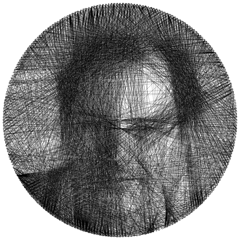
To start off with, we need in image. Here is an old photo of me (when I was younger, healthier, and had marginally more hair). I scaled this to the resolution I was using 1,024×1,024 and converted it to 8 bit gray scale (each pixel 0-255). The code I wrote then read this image and stored it in memory as a 2D array. I elected to invert the image as it was being read so that full black was 255, and full white was 0. In this way the array stored the ‘darkness’ of each pixel.

The next stage was to generated the coordinates of the pins to be used. Using a circle of appropriate radius I calculated the (x,y) coordinates for a series of equi-angular pins that I could nail close to the edge of the table top. When I first experimented, I selected 256 pins to use as, being a power of two, it would simplify the locating of each pin (divide the circle in half, then again, then again …). However, being lazy, I didn’t relish the prospect of having to accurately nail in 256 pins around the periphery of the table top, so google around I found the book binding spines have a collection of open ‘hooks’ I could used as pins, and I could glue these around the edge of the tabletop to make pins 0.25 inch apart very rapidly. The circumference of the table top I obtained meant that I ended up using 233 pin locations.

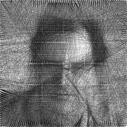
As we will see later, the algorithm does not require that the pins be distributed in a circle, nor that they be equally spaced. As long as you have the (x,y) coordinates of each pin, the algorithm will work. I experimented with different geometries (such as rectangular and hexagonal), and they produced pretty good results, but the circular layout seemed to work best because of how the threads overlapped. The restriction is that the pins should be arranged in a convex polygon arrangement (to stop the algorithm attempting to thread across a void), but a simple modification to the algorithm could be applied to stop this by giving every pixel outside the geometry a special sentinel value (such a negative 1), and any thread that passed through a pixel with this value could be instantly rejected. (Below is one of my experiments using a square layout - some of the aliasing comes from the reduction in resolution).
To start the algorithm, I selected a random starting point. From there, the greedy approach is pretty simple: Where is the best place to thread to next? This can be found be calculating a score for connecting a thread from the current pin to every one of the other pins on the board, and then selecting the pin with highest score.
The scoring I used was simply the average (arithmetic mean), of the pixels that the line connecting the two pins passed through.
(I made a slight optimization in that I didn’t check every destination pin when searching for a candidate; I didn’t bother scoring for any pins +/- a dozen or so pins from my current location; if selected, these would be short links, and not traverse the center of the image).
When a thread passes over the canvas it adds contrast (I painted my canvas board white, and used a black thread). The thread is of uniform density, and adds contrast over it’s entire length. To calculate which pixels the string passes through, I used Bresenham’s line algorithm. This is a very well known algorithm for generating lines in computer graphics. It’s a great algorithm because it’s easy to implement and is fast (in the early days of video gaming and computer graphics it also had the tremendous bonuses of using integers, and if implemented optimally, requiring only addition, subtraction, and bit-shifting. These facts were staggeringly important to the CPUs in the early eighties where floating point operations were costly and slow, or not even available!).
Using Bresenham, the line tracing the source to each of the potential destination pins could be derived, and the pixel values that the string would pass through could be averaged. The path that had the highest average density was selected as the next target destination.
That’s almost the complete algorithm, but account has to be taken for the fact that the string is now on the canvas, and this effect has to be compensated for. Once the final line has been selected, I pass through this line again, and attenuate (reduce the value) of each pixel in the sourcen image that it passes through. I experimented with various attenuation profiles, but in the end I found that simply halving the value of each pixel the line passed through produced acceptable results. Reducing the blackness of each of these pixels means that the application of that thread has been applied to the image and the next best lines to be selected are aware of this.
The question is, when to stop.
If I carried on forever, the final image would just get darker and darker as I wound the string around. I elected to set a threshold (sort of like a temperature in simulated annealing), for the average contrast of the line just added. Again, with experimentation I found that stopping when the average density of the next line was below 40 produced acceptable images (clearly this will depend on the thickness of the string used and the spacing of the pins). To experiment with these values, I wrote code to plot the output to a virtual screen of 10,258×10,258, then plotted the thread as single pixel lines (this approximated the width of the thread to the spacing of the pins, so allowed me to judge the density of the created image). If you are interested, here is the image (warning, it’s a large file).
You can see from the above graph, the temperature initially goes 'up', before falling. This is because I selected the first pin at random!
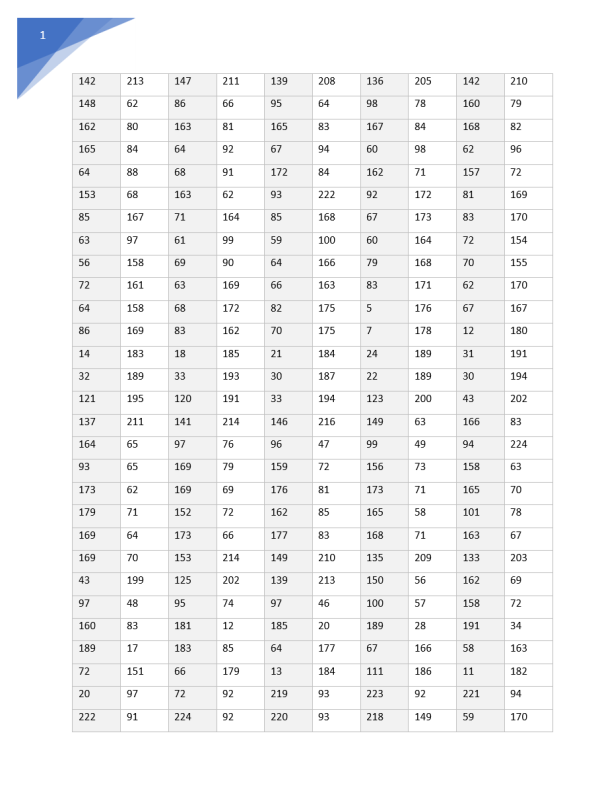
The output of the code is just a series of numbers (instructions), and these are just the pins to wind the thread around.
Building It
Code complete, it was time to have a go at physically making this piece of artwork.
After a little browsing online, I found I could purchase some blank circular table tops from the local hardware store quiet cheaply. I then spray painted the front surface with white paint.
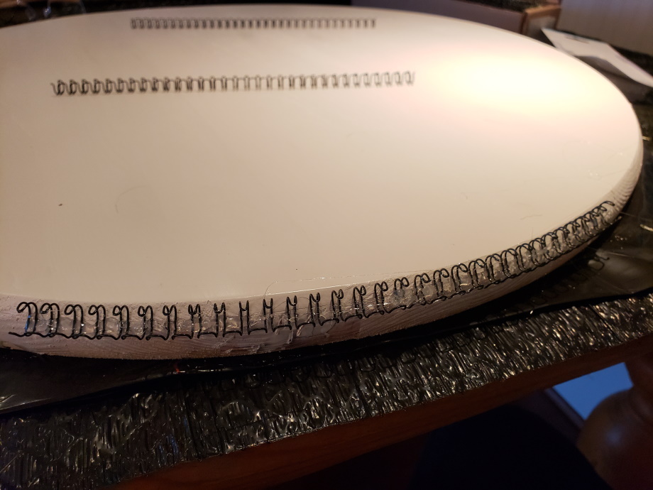
Using a hot glue gun, I affixed a series of wire book binding spines around the circumference. These were also cheap to purchase, held the thread really well, and ensured I did not have to nail hundreds of pins, accurately, around the edge of the board. The hooks on the spines I used were spaced 0.25” apart.
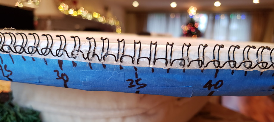
Next, I placed a strip of painter’s tape around the edge and, using a marker, labelled the spines. I elected to put major marks every five pins (knowing that I could interpolate between for the others). This worked out fine.
Finally, I purchased a cheap lazy-susan (a turntable) which I temporarily mounted the table top to. It span very freely, and I was surprised how quickly I was able to thread the artwork, reading the numbers of the list of instructions, I’d spin the table, wind the thread, then read the next instruction (I did think of using text-to-speech to read out the table of instructions, but found out that this was not really necessary). I was able to thread the couple of thousand threads needed in just a couple of hours.
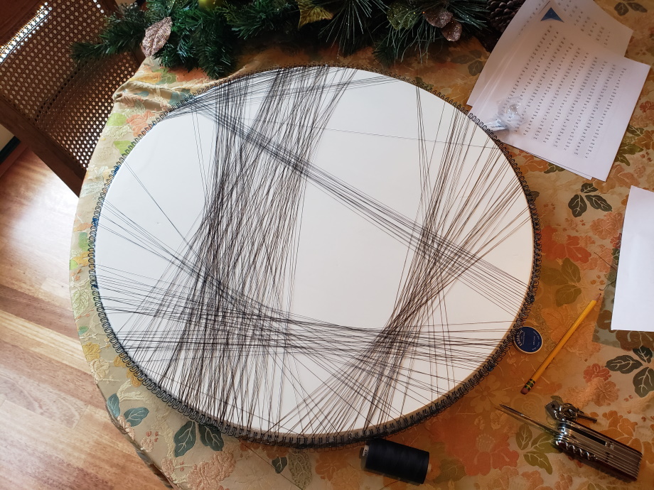
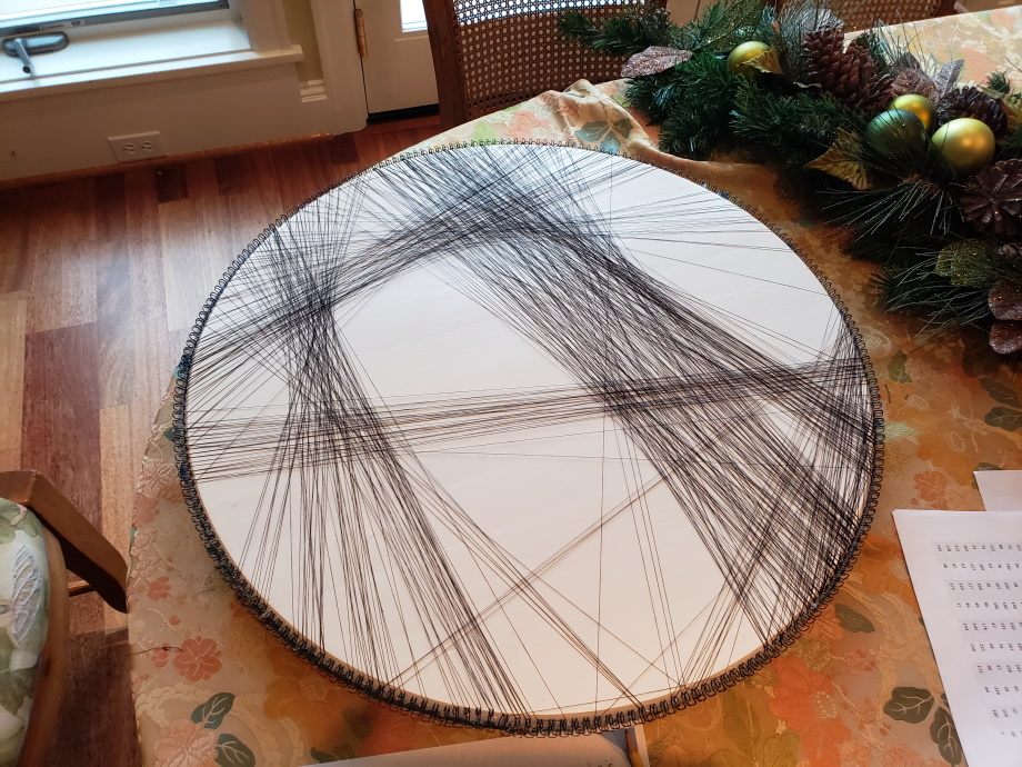
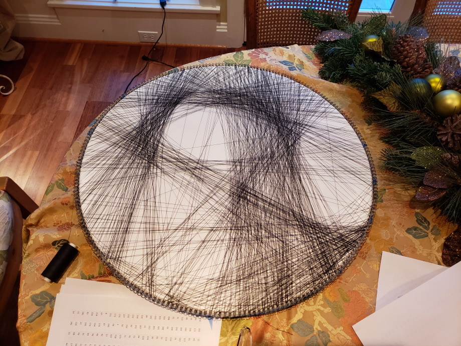
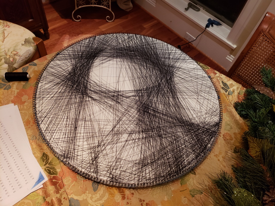
The Result
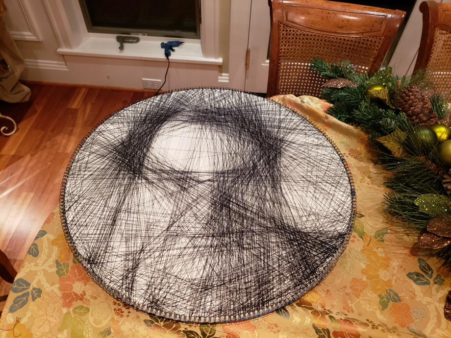
I’m really pleased with the results, and how the final image came out. I do, however, have a confession to make about the final image. I made a rookie mistake, can see see what it is?
The mistake is that I labelled the pins winding clockwise around the table using the tape, but the output instructions were written for pins labelled coutner-clockwise. The image is the wrong way round! You'd better look at in a mirror, as I have no desire to unwind and rethread it.