Stereograms
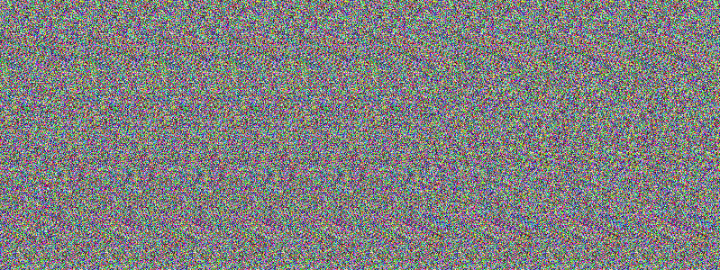
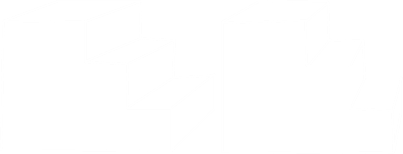
This week I'm going to talk about Random Dot Autostereograms. Here's an example below. Can you see it?
Some people can see these images right away, others take a little time, and a small percentage of folks never seem to be able to master viewing them. If you can't see it, the dots above contain a four letter word, with a pseudo-3D effect so that, even though your screen is flat, the letters appear to be offset and at a different 'depth' to the background around them.
Autostereograms became popular 20-30 years ago in books and posters (many under the moniker MagicEye), but they were invented decades before this in 1959 by Dr. Béla Julesz, a Hungarian professor.
Here's another example. This one uses colors, but the effect and mechanism is the same.
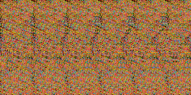 Image: Fred Hsu
If you can't see the image, try relaxing your eyes and focus on a point behind the screen (at a distance approximately the same behind the screen as you are infront of it). If you get it correct, it's like you are looking through the screen as a window at the object behind it.
The image tricks the brain into thinking it is looking at a 3D scene. Once you can see the image, if you move your head from side to side, you don't get a different perspective on the scene, it simply translates in a weird way.
Before we delve deeper into autostereograms, let's take a look at human vision and other mechanisms to allow the brain to perceive depth.
Depth Perception
How does the brain perceive depth? There are many techniques which are combined to give us clues:
Size - We know the typical heights of things like people, cars, and houses. When we see a small person, our brains can approximate and interpolate how far away they might be. Sizing clues can be both relative and familiar size comparisons.
Perspective - The property of parallel lines converging in the distance, at infinity, allows us to reconstruct the relative distance of two parts of an object, or of landscape features. For example standing on a straight road, looking down the road, and noticing the road narrows as it goes off in the distance.
Occlusion - Nearer objects pass in front or obscure more distant objects.
Shadows - The way that light falls on an object and reflects off its surfaces, and the shadows that are cast by objects provide an effective cue for the brain to determine the shape of objects and their position in space
Atomspheric - Due to light scattering, objects further afield tend to have lower contrast, In computer games, graphics engines apply a distance fog effect to emulate this.
All the above clues effect provide clues to augment our depth perception, but the brains biggest indication comes from an effect called Stereopsis. We have two eyes, which gives us binocolar vision. Each eye sees a slightly different image, and the brain can combine these to make a depth map of what is in front of us. (In addition, muscles in the eye can converge the eyes to bring them both pointing at the same target, and this can give the brain an additional clue of distance when objects are reasonably near).
Stereopsis
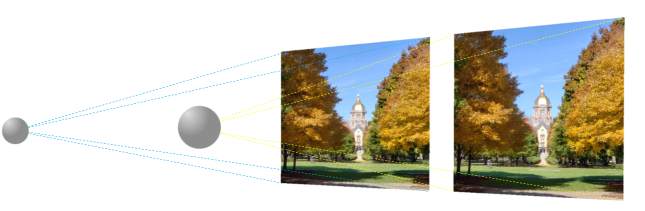
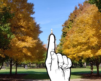
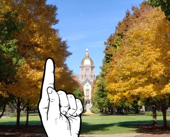
Because our eyes are separated by a small distance, when we look at an object, each eye captures a slightly different view (stereo disparity). The closer an object is to our face, the higher the disparity.
You can see this quite simply by closing one eye, and holding a finger in front of a distant object (such as a tree, tower, or building), and observing the scene through one eye. Then, closing that eye, and opening the other. By alternating between the two eyes, you can see the different perspective each eye has on the scene.
Returning again to video games, before full 3D titles, side scrolling 2D games used a technique called Parallax Scrolling to give the effect of depth, and some idea of motion or speed. Multiple layers of graphics scrolled in the background at various speeds (as if each was painted on a layer of glass). Those layers 'far away' moved slowly, and were typically distance-fog contrast adjusted. Layers a little nearer moved a little faster, and those close to the foreground moved close to the speed the play area was been scrolled at.
 Image: Wikimedia
The example on the left shows parallax scrolling with three layers.
Stereo Images
If we can find a way to deliver two correctly disparate images of a scene (distinctly) to each eye, we can trick the brain into believing it is looking at a 3D scene and we can perceive depth, even if it is not present.
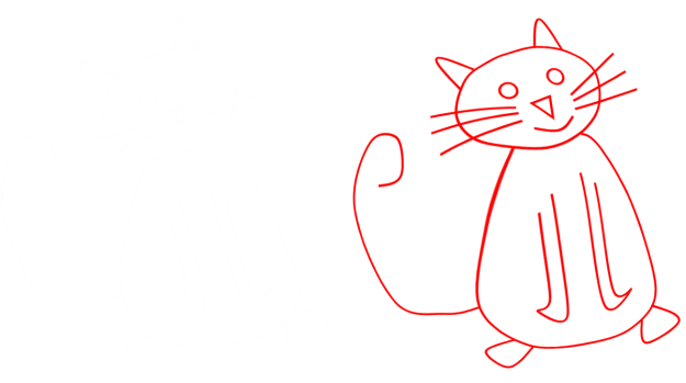
To see this cat in 3D, we need to find a way to deliver the one image to the left eye, and one to the right.
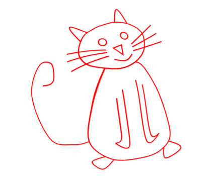
If we are allowed to use additional hardware, this is a relatively easy task.
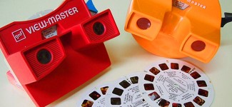
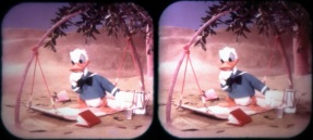
There are a variety techniques that have been used over the years. When I was a child, my parents bought me a View-Master toy. These used media disks which contained pairs of stereoscopic transparent color photographs (seven pairs on each disk), that allowed the viewer a binocular slide show.
Optics in the View-Master deliver a stereoscopically distinct image to each eye, and the brain can combine these to make a 3D image.
View-Master is still available today, and even the new models still play the original media disks.
Whilst the View-Master was popular in Twentieth Century, the idea was not new. As early as 1833, Sir Charles Wheatstone, was experimenting with photographs taken from slightly different positions and combining them with a device he called a reflecting mirror stereoscope. His research earned him the Royal Society Medal. His invention was also very well received by Queen Victoria.
In fact, stereo photography flourished alongside mono photography in the early years of the camera. It was only with the advent of movies that stereo photography declined!
Anaglyphs
Another popular technique used was the Anaglyph. These required less sophisticated technology to replay (just a pair of tinted glasses), but had the disadvantage of not being able to display full color. Below is an example of a view of the surface of Mars.
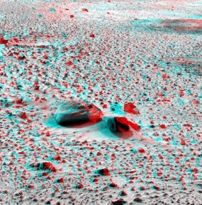
Anaglyphs work by combining two, chromatically disparate, stereo views into a single image. Filtered lenses (typically red/cyan, but other variants are sometimes seen, such as red/green), block out the image to the other eye. Because of the filter, each eye is only able to see the shaded image it is intended to receive.
Because of the cheapness of the glasses, this technology is still popular today. Anaglyphs can be printed, displayed on computer monitors, or even used for television or movies. Tweaks can be made to attempt to give false colors*, but anaglyphs are not able to display full color images.
*Our brains are very clever, and can watch false color tinted gray scaled images and interpret these closer to what that natural colors should be.
Color?
To get full color, more technology is needed. There are active and passive approaches. A passive approach is through the use of polarizing filters. This is the predominant technology used in movie theaters which present 3D movies.
To display a 3D movie, two projectors are used. In front of each is placed one of two orthogonal* polarizing filters. Each lets through only light that is polarized in the plane of the filter. The viewers wear a pair of glasses, one of each lense of which is the corresponding, similarly aligned, polarizing filter. Only light from the projector appropriately aligned with the filter is passed, and so each eye can see a distinct stereo image. This technology is passive (the glasses have no active component), but two projectors are needed†, and attempting to view the movie without glasses just results in a blurred-looking double image mess. Polarized projected movies, however, are full color, and multiple people can view the same projection at once.
*A slightly different variant uses circularly polarized filters instead of linear polarization. This has the advantage the a slight tilt of the head from side to side does not cause cross-channel bleeding (but tilting more than a small amount still breaks the 3D effect as the images don't correspondingly align).
†Single projector systems are now available that use a single polarizing filter which can be rapidly (electrically) flipped in orientation. Coupled with a fast digital projector in synch, only one projector is needed.
Active Glasses
Instead of using polarized filters, and passive glasses, another alternative is to use active glasses. These glasses have built in batteries and liquid crystal lenses that can be darkened with an electrical pulse. Alternately, each lens is blackened, and made clear, at a very high refresh rate. This is synchronized with the projector(s) using a technology such as infra red pulses or radio waves. Active shutter glasses are more expensive, and the refresh rates need to be very high to prevent noticeable flicker.
Full color 3D without glasses
Technology exists to generate separate images without the need for special glasses. They are not perfect, but they interesting to view if you ever encounter them.
One system is through the use of a lenticular lens coating on the front of the screen. These miniature lenses refract light from alternate pixels in alternate directions.
This technology is not new; you've probably encountered it before on the backs of cereal packages, baseball cards, postcards, or stickers, as they can be used to produce animated 'magic' stickers that change depending on the angle you look at them. They are characteristically ribbed on the front surface.
Another method used instead of minature lenses is the Parallax Barrier. This can be either fixed, or active (LCD shutters) and acts like a mask, blocking out light from the non-appropriate angles. This technology is used to produce the 3D display on the Nintendo 3DS system. Positioning of the viewer is very critical to enable the display to function correctly (which makes it perfect for hand-held video games played by just one person), but makes viewing angles harder for use in a room wide TV set-up to be viewed by many people.
The poor viewing angle concept can be exploited for a creative application of this technology. The 'left' and 'right' components of the display don't have to display the same source. In modern cars that have a center mounted video display, different images can displayed to the driver and the passenger. When looking at the screen, the driver can view driving specific information, or view a GPS, whilst the passenger can be watching a movie (that would otherwise be dangerously distracting to the driver). Each viewer gets a different image.
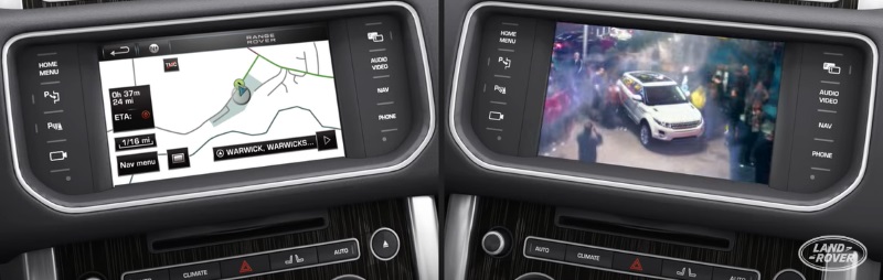
An example is shown above showing the Range Rover's Dual View system.
Entering VR
Recently, we now have available sufficiently powerful (and relatively cheap) computers, optics, and high pixel density displays. These combine to make the perfect storm which allows for the creation of virtual reality devices. We're still in the early stages of this technology, but it's incredibly exciting.
Rather than displaying pre-rendered media from a fixed perspective, virtual reality allows freedom and interaction. A VR headset contains two displays and these are connected to a pair of graphics boards*. These boards render, in real-time, the scene that would be visible from that eye using a 3D model of the scene.
*Or a single powerful board that drives each display.
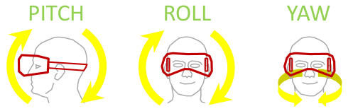
Entry level systems (such as Samsung Gear and Google Cardboard), support three degrees of freedom. They are more analogous to electronic View-Masters (but not restricted to a fixed scene). Wearing them is like being in the middle of a giant sphere, onto which is projected the scene. Wherever you look, the computer tracks where your head is pointing and renders the scene you would see and paints this on each display. They are called three degrees of freedom because the device tracks the Pitch, Roll, and Yaw of your head.
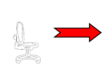
Imagine sitting on an office chair with one of these entry level devices on your head, it's like having a View-Master, and being able to point it anywhere and see what you wanted to see. Neat! However, if someone were to push you around the room on the office chair, your view would not change. To enable the view to correctly trace, we require more degrees of freedom tracking …
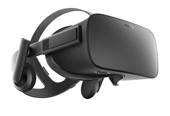
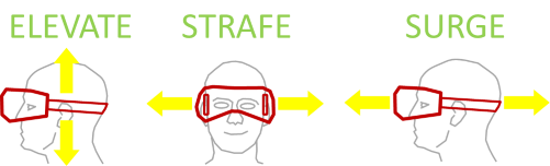
Enter now the high end VR devices (such as Oculus Rift, and HTV Vive). These devices track six degrees of freedom. You may have also heard these devices referred to as Room Scale. In addition to the three rotations degrees of freedom: Pitch, Roll, Yaw, these device track the three translational types of movement: Elevating, Strafing, Surging. With a six degree freedom setup, you can step from side-to-side to view the scene from that position, or lean-in to get a closer look (or lie down, jump, or stand up to get a different take on the scene).
Room scale systems use transducers to track where you are in the room, and sensors on the headset track rotations. The VR system can thus render the scene as it should be from exactly where you are looking.
Return to Stereograms
OK, back to autostereograms. We've seen above that, to generate a 3D image, we need to get a different image for each eye. A single image random dot autostereogram is a mechanism for doing this that does not require any additional hardware.
Our minds have an ability to combine two slightly different images of the same scene and derive the depth map. This is called fusion.
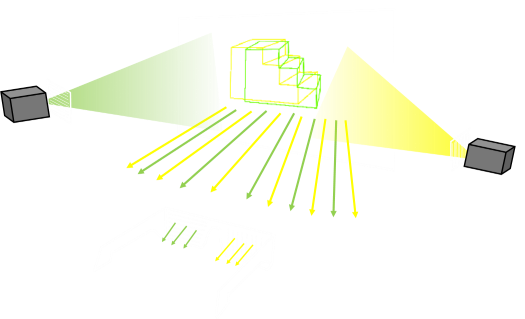
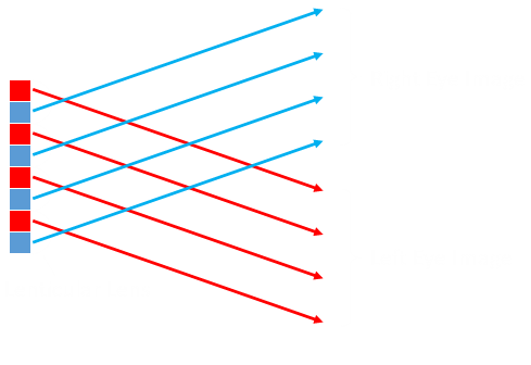
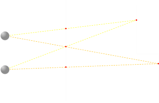
In the diagram below, we have a 3D model on the right, the screen in the middle, and our eyes on the left. Whilst the screen is where we will be generating the image, imagine, for now, that it is a sheet of glass. We can trace rays of light and find out what projection the model has onto this sheet.
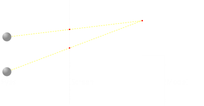
If we look at one particular part of the model (shown by a red dot), then tracing the rays, this corresponds to two red dots on the screen. If we color both of these pixels the same color, then each eye would see the color they expect to see. So far so good …
Now imagine we have two points (red and green) that we need to render. If we ensure they are rendered with the same colors then, our brains, using fusion, recognize they are the same point and correctly tell our brain what depth they should appear to be. At first glance it seems that all we have to do it calculate the correct location to project each point of the model onto the middle plane and we are done …
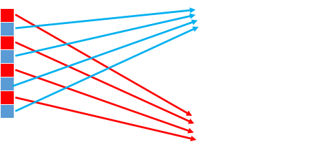
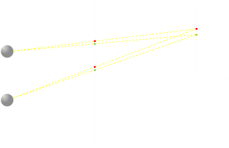
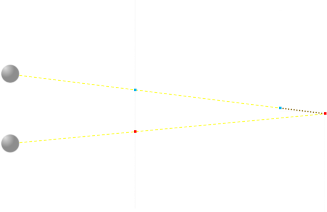
However, we quickly come upon a problem. Here are two different points we are trying to project and render on the screen. The yellow ray lines show two locations that need to be the same color, however, we also need to make sure the pixels from the orange ray lines are also so the same color. We can do this by making sure all three pixels are renderer the same way. When looking at the pixel traced by the yellow rays, the top and the middle pixel are fused, when looking at the pixel traced by the orange rays, the middle and the bottom pixels are fused.
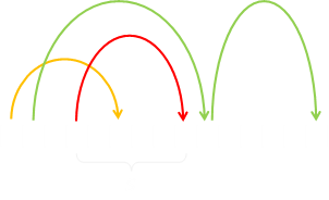
We can do this by creating a linked-list daisy chain of all the pixels that need to be the same color. Our eyes are horizontal, so we are only looking for disparity in the horizontal plane, which makes the code to generate stereograms pretty efficient. We scan the scene from top to bottom, row-by-row, and for each row, starting at the left hand side we move across the model, pixel by pixel, finding out which two pixels on the plane of the screen each model pixel projects to. For fusion to occur, these two pixels need to be the same color.
Using an array, we can keep track of all the pixels that need to be the same color. We call this a dependency array. When we determine a pair of pixels that need to be the same color, we can update this array, cascading through the dependencies, as necessary, to ensure that every appropriate pair of projected pixels is the marked to be the same.
Once the row is totally scanned, and all dependencies determined, we can render it by starting at the opposite edge going back the other way. If a pixel is not set, we give it a random color. If it has no dependencies, we move on. If it has dependencies, in addition to giving it a random color, we trace through the dependency array and mark every pixel that needs to be the same as this pixel with the same color.
To generate black and white stereograms, for a pixel that is not dependent on another pixel, we just flip a coin. To generate colored stereograms we select a random color.
Math
Each pixel of the model corresponds to a pair of pixels on the projected plane. The distance between these two pixels is determined by geometery.
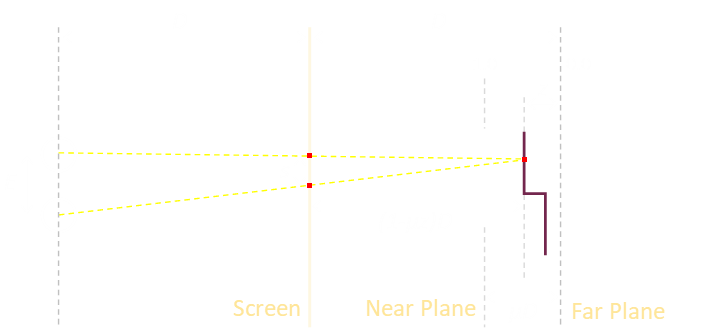
In the diagram above, E is the distance between the eyes of the viewer, and D is the distance between the viewer and the screen. We can say the far plane (furthest virtual distance from the eye) to be the same distance D away from the screen backwards, and we'll set near plane (shallowest depth object) to be some percentage of this distance. We'll define this percentage as a ratio µ (All of these are parameters that can be tweaked, but I found a value of µ=0.33 worked well).
Z is the coordinate for the depth ranging from 1.0 for points on the near plane, to 0.0 for points at a depth on the far plane.
The distance we need to determine is s, the separation distance between the two pixels which need to be rendered the same color. This can be determined using similar triangles.
The larger triangle has the base E, and a height equal to the distance to the screen plus the distance from the screen to the virtual point. The smaller, similar, triangle has a base s, and a height the distance from the screen to the virtual point.
Rearranging we can find a formula for s. Interestingly D, the distance from the screen totally cancels out. It is not important how far away from the stereogram we stand.
We need to project each point on the model to two points on the screen. The y-coordinate of each point passes through unchanged, and the x-coordinate is modified based on the equation above. The two pixels (call them left and right), need to be s pixels apart, we specify make left coordinate to be XL = x-(s/2), and the right to be XR = XR+s
Crisp Edges
There are just a couple of other cases we need to deal with. The first is trivial. This is when either XL or XR is off the edge of the screen. When this is the case, we don't need to worry about the dependency of the non-visible pixel.
The second is more subtle, and this is hidden dependency removal.
In the diagram above, using our basic formula, we would determine that the red pixel should be placed twice on the screen. However, if you look closely, the top ray is occluded by other parts of the model. If we added the lower point to the dependency array, then we'd falsely link them together and cause fusion that should not be present. In this case, the dependency should not be present and constraint pairing these two pixels not recorded. If the constraint were kept, the edge would have 'echoes' beyond where it should be.
The lower pixel is free to be it's own color, and thus not fused into a false echo/fuzzy edge.